Page 1 of 1
Getting the boards to fit with the D13
Posted: Thu Sep 06, 2018 9:25 am
by nama
Ok, now that I have built the D13 and got my system back up an running reliably with a new floppy drive, it's time to put everything back together...there is only one problem:

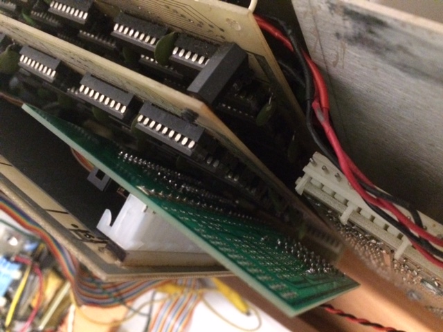
- IMG_7204.JPG (116.58 KiB) Viewed 9074 times
- IMG_7205.JPG (117.21 KiB) Viewed 9074 times
the D13 buts up against the memory board that sits directly below the 505b board. Unfortunately this means the boards can't sit parallel, and the 505b board has to jut out at an angle. Because of this angle the long thin bolt holding the the boards together and that secures them to the top case isn't long enough. I thought about rearranging the order of the boards but I can't see how that would work either.
Has anyone come across this issue before? Any ideas would be greatly appreciated.
Cheers
Phil
Re: Getting the boards to fit with the D13
Posted: Thu Sep 06, 2018 3:17 pm
by Klyball
is there room if you put it on the other side of the board, I designed this for the 610 , I think jeff got his to fit
Re: Getting the boards to fit with the D13
Posted: Thu Sep 06, 2018 6:54 pm
by Jeff
Sadly, No.
I did not get mine to fit. I did get it to work, but not fit. I was planning to have a new larger case made for it.
/Jeff
Re: Getting the boards to fit with the D13
Posted: Thu Sep 06, 2018 9:54 pm
by Klyball
is there room for it in there anywhere, could make up a cable
Re: Getting the boards to fit with the D13
Posted: Fri Sep 07, 2018 12:05 am
by nama
Thank you all for the replies.
I think my three options are:
1) Make up a cable (as you suggest) and mount the D13 somewhere within the case. Need to see if there is room.
2) Desolder the header pins off the 505b board and mount them on the parts side, then mount the D13 on the reverse (parts side) side of the 505b. Will need to take some measurements to see if this will work. May be tight. One issue is the trimmer pot will be inaccessible, or at least very very hard to get to.
3) Desolder the header pins off the 505b board and desolder the molex connectors from the D13, them solder them both back on their respective boards, but on the other side. This will solve the access to the trimmer pot issue, but will add more height, so may not fit.
4) Replace the two ram boards with a single GW-OSI-RAM1 Universal RAM Board (from glitch works). This should give plenty of space.
Hurumph...
Philip
Re: Getting the boards to fit with the D13
Posted: Tue Sep 11, 2018 1:25 am
by MK14HAK
Phil, I'm after a GW-OSI-RAM1 Universal RAM Board, lets know if you decide on this option (more reliable I would think) and Ill order among other boards if you like.
Re: Getting the boards to fit with the D13
Posted: Tue Sep 11, 2018 3:43 am
by nama
Mike,
Sounds like a plan
Re: Getting the boards to fit with the D13
Posted: Tue Sep 11, 2018 1:24 pm
by dave
I wonder if right angle connectors could possibly free up a enough space to fit the D13, and other paddle boards, between boards:
Molex# 26-60-3120 , Mouser # 538-26-60-3120,
Molex# 09-48-1124, Mouser# 538-09-48-1124
Re: Getting the boards to fit with the D13
Posted: Wed Sep 12, 2018 10:18 pm
by nama
Hi Dave,
That could possibly work on some machine. Maybe the C8 etc.
But I don't think it would work on the C4/C2 as there probably isn't enough space.
Phil