Now that I have my machine mostly working, I want to try to load Basic through the serial port. I have the basic Hex that I downloaded from the net so I'm ready to go.
My questions are:
- Do I load Basic at $A000 onwards
- Do I then launch Basic from with a .A000G ?
I have seen reference on the web saying that a cold start entry point is $BD11 and a warm start is at $A274, but these were from a 1P page. I have tried all three but the C4-2P just seems to hang.
Phil
Loading basic through the serial port
-
nama
- Posts: 369
- Joined: Wed Mar 30, 2011 9:44 am
- Location: New Zealand
- Contact:
Loading basic through the serial port
2P (1mhz 32k) - 502 + 8k + CEGMON + garbage collector fix BASIC, D&N MEM-CM9 + 24k, 540 (mono) [SOLD]
4PMF (2mhz 24k) - 505, 540, 527, D13 + 5.25" + Gotek
Superboard RevD - CEGMON + 610 board 24k + D13
Spares - 3 x 527, 1 x 505, Backplane
-
dave
- Site Admin
- Posts: 717
- Joined: Tue Sep 09, 2008 5:24 am
Re: Loading basic through the serial port
Did you check the jumpering of your 527 board? Don't forget that to run BASIC-in-ROM, you need a place to put the BASIC at $A000, and also RAM at $0000. The three 8K blocks on the 527 can be assigned on any 8K boundaries, so you could put one at $A000, and the others at $0000 and $2000, but I doubt it came configured that way.
Also, you will need to make sure your ROM monitor is configured to support ROM Basic. The C2/4/8 ROM has 8 blocks of 256 byte firmware, which are mapped to FThere will be a little jumper to wire the "FF00 select" line to one of the 8 blocks in the ROM. You will need to switch the jumper to point to the "C/W/M?" block. Looking at the synmon hex dump, it appears that H/D/M is in the highest block, and C/W/M is in blocks 1 and 4. There is a jumper block feeding the "FD00", "FE00", and "FF00" select signals to a 74148 decoder chip. You want to move the jumper to move the "FF00" line from pin 10 of the 74148 and onto pin 3 or 13; if that doesnt work, try all the other inputs until you get an H/D/M.
This scheme was to map the ROM around a cassette port at FC00. The C1 moves this port, and doesn't need do this, so it can use the whole ROM without any jumpering.
If you want to burn a 2716 instead, there's a jumper to select between 2316 and 2716, and then you can download the ROM contents from the Monitor ROMS section of the software page, there is a download link for a SYN600 ROM. It contains all the monitor code broken down into 256b chunks, which can be re-assembled to put the BASIC-in-ROM ("C/W/M" $FF00) where you want it.
Good luck!
Dave
-
nama
- Posts: 369
- Joined: Wed Mar 30, 2011 9:44 am
- Location: New Zealand
- Contact:
Re: Loading basic through the serial port
Hi Dave,
Thanks for the reply. I was thinking my issue was a simple one, but it seems to be a little more complex than I expected.
I had to re-read your response 3 times before I understood it.
I do have a second 527 board that when installed gives my weird graphics, however I believe that is a power issue as these cards use a lot. I have a 6amp switcher on order and should be here soon. hopefully that will help. I only mention this as I will eventually have 48k installed and I'm certain the A000 space must be addressed when both cards are installed and working. I'll confirm that once I can find the jumper info.
Now I think my best option is to burn a 2716 Eprom and re-jumper the board for this. I downloaded the SYN600 rom as you suggested, and can see the 8x256 byte components. So this is the bit where I'm a little confused.
the 2716 is a 2k eprom so I can put all 8x256bytes into it. I'm going to make a guess and say this is the order in which I should do it (I'm probably wrong):
Block 1?
Block 2?
Block 3?
Block 4?
Block 5- 00's
Block 6 - c2_key_FD00
Block 7 - c2_65v_FE00
Block 8 - c2_cwm_FF00
As you can see I have put the CWM in the last block (FF00). I'm uncertain what goes in banks 1 the 4 (lower half), but my guess is it doesn't matter and maybe 00's are ok (or maybe just repeat the upper half again just to be safe).
Well these are all assumptions based on your reply, and also there is a 'Make file' included in the ROM download with gives some clues. Hope I'm close.
Again, I'm guessing that once I get this part working I can then transmit the Basic code via serial in monitor and once loaded it will give me the Basic prompt. Or maybe I need to do a reset and press C from the CWM prompt.
...now to look for the jumper to change to 2716
Thanks again
Philip
2P (1mhz 32k) - 502 + 8k + CEGMON + garbage collector fix BASIC, D&N MEM-CM9 + 24k, 540 (mono) [SOLD]
4PMF (2mhz 24k) - 505, 540, 527, D13 + 5.25" + Gotek
Superboard RevD - CEGMON + 610 board 24k + D13
Spares - 3 x 527, 1 x 505, Backplane
-
dave
- Site Admin
- Posts: 717
- Joined: Tue Sep 09, 2008 5:24 am
Re: Loading basic through the serial port
The circuit is a little odd, in that the ROM doesn't just map to the address space. It's purpose is to make sure that the computer finds the keyboard routine at $FD00, the 65V monitor at $FE00, and the boot routine at $FF00. To save money, OSI used the same BASIC ROMs and monitor ROMs throughout their line (even to the point of introducing new computers with the same age-old bugs.). Since the BASIC ROMs and disk format were the same for all hardware, these routines served as a primitive BIOS for the BASIC, and disk booting. OSI wanted to be able to switch out these routines based on the model of computer. The addressing is complex on a C2, because there is a cassette/serial port at $FC00. On a C1, the port was elsewhere, so no complex jumpering was needed.
The decode circuit produces three select signals, FF00, FE00, and FD00. There is a jumper block that will allow you to tie each of those signals to any of the 8 blocks in the ROM. So when an address in the FF00-FFFF range is selected, FF00 is active. It will be tied to one of the 8 lines of the 74148 priority encoder, which then selects on of the 8 blocks in the ROM via 3 address lines.
So, you can put any block at FF00, any other block at FE00, and any other block at FD00, just by changing those jumper wires. So as long as your PROM has the C/W/M block, if you know that block number, you can jumper the FF00 line to the priority encoder input for that block. From your pictures, that line is currently jumpered to an H/D/M block. The FE00 and FD00 lines are already jumpered to the 65V and keyboard blocks.
Even if you didn't have dumps of SYNMON1 or SYN600 to examine, you could still try jumpering FF00 to each of the 5 unused 74148 inputs, until you boot to a C/W/M.
The reason the Syn600 image is chopped up into parts like that is because I modified my C2 to use a CEGMON ROM, which requires the entire 2K except for the single block at FF00. One I had that addressing scheme in place, I no longer had the OSI jumpering scheme, and so if I wanted to go back to the original code, I was forced to actually move the 256 byte blocks around in the ROM so the right code would be at FD00, FE00, and FF00. I posted some instructions on the mod, but I wouldn't try to do it. I'd recommend sticking with the original ROM, and just moving one jumper.
Can you post the version of your monitor ROM?
You will still have to jumper one of the 8K blocks on the 527 RAM board to locate it at $A000, if you want to load BASIC there.
Best regards,
Dave
-
nama
- Posts: 369
- Joined: Wed Mar 30, 2011 9:44 am
- Location: New Zealand
- Contact:
Re: Loading basic through the serial port
Just a quick reply before I head off to work.
Firstly, thanks for all the great info. That makes perfect sense now.
...Look what I just found.
http://www.go4retro.com/wp-content/uplo ... G_3076.jpg
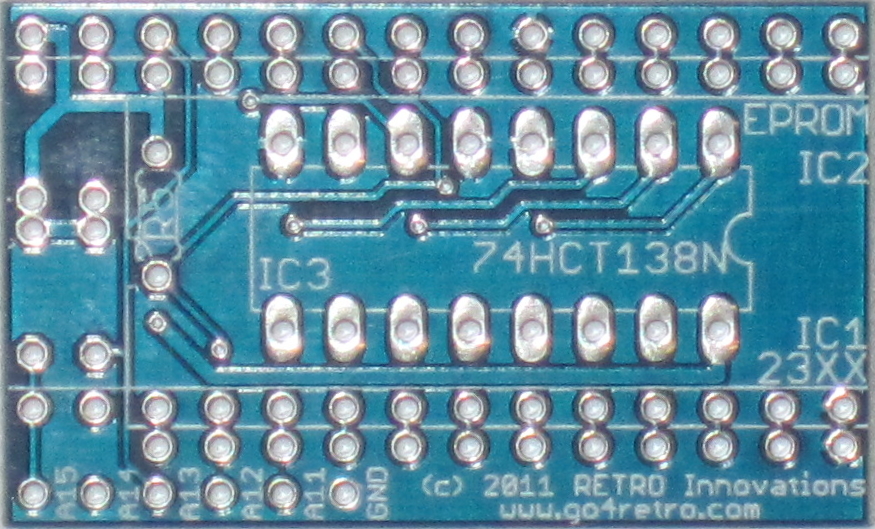
Seems Jim Brain has literally just finished a limited production of 23xx adaptors, how timely is that. I was thinking I'd get a couple, and try one out in the 2P. Hopefully I'll be able to burn multiple configuration of SYN600 to an eprom and this adaptor will allow me to easily switch between C/W/M and H/D/M easily without redoing any jumpers.
I was looking at my jumpers again last night. It seems that someone has had a lot of fun already cutting traces and adding jumpers, so I'm a little reluctant to start moving stuff around again. Look here:
and
This adaptor may just be perfect for me. What do you think?
Cheers
Phil
Firstly, thanks for all the great info. That makes perfect sense now.
...Look what I just found.
http://www.go4retro.com/wp-content/uplo ... G_3076.jpg
Seems Jim Brain has literally just finished a limited production of 23xx adaptors, how timely is that. I was thinking I'd get a couple, and try one out in the 2P. Hopefully I'll be able to burn multiple configuration of SYN600 to an eprom and this adaptor will allow me to easily switch between C/W/M and H/D/M easily without redoing any jumpers.
I was looking at my jumpers again last night. It seems that someone has had a lot of fun already cutting traces and adding jumpers, so I'm a little reluctant to start moving stuff around again. Look here:
- Jumpers.png (149.73 KiB) Viewed 15052 times
- Cut_traces.jpg (65.35 KiB) Viewed 15052 times
Cheers
Phil
Last edited by nama on Sat Jan 07, 2012 2:17 pm, edited 2 times in total.
2P (1mhz 32k) - 502 + 8k + CEGMON + garbage collector fix BASIC, D&N MEM-CM9 + 24k, 540 (mono) [SOLD]
4PMF (2mhz 24k) - 505, 540, 527, D13 + 5.25" + Gotek
Superboard RevD - CEGMON + 610 board 24k + D13
Spares - 3 x 527, 1 x 505, Backplane
-
dave
- Site Admin
- Posts: 717
- Joined: Tue Sep 09, 2008 5:24 am
Re: Loading basic through the serial port
I think the adapter would work fine. But then again, you could just move the jumper going to pin 20 of U2D from pin 4 of U4E to pin 2 of U4E. I suppose it's a good policy not to fiddle with something that is working. For me, though, the whole appeal of the OSI, as opposed to an Apple, was always that it seemed to have a special gravitational pull for solder and blue wire :0)
-
nama
- Posts: 369
- Joined: Wed Mar 30, 2011 9:44 am
- Location: New Zealand
- Contact:
Re: Loading basic through the serial port
Although I have contemplated doing the 2716 mod multiple times over the past 3 days, I have restrained myself. As you say, the machine is working now, and I don't really want to mess with it too much especially seeing as the area in question has already had some serous hacking done to it...
I'm going to wait until Jim brain has his 23xx adaptor boards ready and use one of these to install a larger eprom with a rotary dial to switch between C/W/M and H/D/M. I think this is the simplest and ultimately most flexible solution. Not to mention my Data IO 29b eprom burner is hidden away (it's massive, so hiding it anywhere is actually quite a feat) in a mass of boxes somewhere, and not easily accessible. I do have my Needham EMP-20 at the ready, but it does not burn anything smaller than 2732's.
As for getting the case sand blasted, I'm having trouble finding anywhere remotely close that can do it. I thought this may be a problem.
I also need to build a small aluminum bracket to mount the switcher, and it's also proving to be difficult. Some of the problems associated with living in Tokyo. Now If I was back in New Zealand I'd have no problem getting any of this done, but on the other hand I wouldn't be living 10 minutes from Akihabara. Take the good with the bad.
2P (1mhz 32k) - 502 + 8k + CEGMON + garbage collector fix BASIC, D&N MEM-CM9 + 24k, 540 (mono) [SOLD]
4PMF (2mhz 24k) - 505, 540, 527, D13 + 5.25" + Gotek
Superboard RevD - CEGMON + 610 board 24k + D13
Spares - 3 x 527, 1 x 505, Backplane
-
dave
- Site Admin
- Posts: 717
- Joined: Tue Sep 09, 2008 5:24 am
Re: Loading basic through the serial port
Sounds like a good plan. Don't forget, you will still need to set the jumpers on the 527 board to have a place to put the BASIC interpreter.
Since you have a 505 board that already has a floppy interface and boot code, perhaps it would be no harder for you to locate a 3.5" internal floppy, build up a data separator (found in the PEEK(65) journals), a floppy cable, and have a floppy based system. At least that way you wouldn't need to fiddle with the EPROM.
Dave
-
nama
- Posts: 369
- Joined: Wed Mar 30, 2011 9:44 am
- Location: New Zealand
- Contact:
Re: Loading basic through the serial port
Yes. I think I'm definitely going to build a data separator sometime in the future. I've even got my eye on a Shugart SA-400 drive for the machine. I've had a look at the article and it doesn't look too hard to build, but for now I just want to play with BASIC for a bit, and changing out the EPROM sounds like the easiest thing.
Anyway, maybe you can help me with another issue. I came across a program in OSI-SSJ-V1N3-09_1977.pdf that allows you to test the memory. This is something I wanted to do to be sure the machine is working to full capacity. I have typed this out and transferred it to the C24P via serial, and it seems to work well. I decided to test RAM from 0400 (the test prog resides from 0200 to 0400) thru 6000. I still presently only have the one 427 board installed witch is fully populated with 24k. I get errors at:
441B
451B
461B
Initially the program would halt with an error at location 441B and thought it was possibly just a bad RAM chip, and I guessed it was maybe the 3rd RAM chip on row E (E3?). I moved some of the RAM around to check my theory, however the problem still persisted. I then started the RAM check from 4500 and found another error at 451B. Ok I thought, thats probably still the same bad IC. Then I started it again at 4600 and came across the error at 461B. Now as far as I know that address would be in a completely different RAM chip (maybe I'm wrong?), so that blows my theory. If I start the test at 4800 thru 6000 then everything seems fine and the RAM checks out ok. The fact that they are all erring out at xx1B is also a little baffling.
One other clue is that if I try to load 00 into 441B and read the contents back it reads 40. if I do it with 11, I get 41 back. The first number always seems to be a 4. I'll need to do some more testing to be sure, and I haven't checked the other addresses yet either.
EDIT: I just put 00's into all three addresses, and read the contents out again and they are all 40's
Just wondering if you had any insight into this problem.
Cheers again.
Phil
Last edited by nama on Mon Oct 31, 2011 12:03 pm, edited 2 times in total.
2P (1mhz 32k) - 502 + 8k + CEGMON + garbage collector fix BASIC, D&N MEM-CM9 + 24k, 540 (mono) [SOLD]
4PMF (2mhz 24k) - 505, 540, 527, D13 + 5.25" + Gotek
Superboard RevD - CEGMON + 610 board 24k + D13
Spares - 3 x 527, 1 x 505, Backplane
-
nama
- Posts: 369
- Joined: Wed Mar 30, 2011 9:44 am
- Location: New Zealand
- Contact:
Re: Loading basic through the serial port
Just another quick update. I have been testing the memory and these are the locations that seem to error out:
441B
443B
449B
44BB
451B
453B
459B
45BB
461B
463B
469B
46BB
471B
473B
479B
47BB
Before 441B and after 47BB the memory tests ok. Seems like a fairly consistent pattern in what address are screwy .
Also trying to see any pattern in how the hex number changes after it's been entered into 441B then read back out:
ff -> ef
44 -> 44
bb -> eb
10 -> 40
77 -> 11
11111111 -> 11101111
01000100 -> 01000100
10111011 -> 11101011
00010000 -> 01000000
01110111 -> 00010001
I can't see any patterns here unfortunately
2P (1mhz 32k) - 502 + 8k + CEGMON + garbage collector fix BASIC, D&N MEM-CM9 + 24k, 540 (mono) [SOLD]
4PMF (2mhz 24k) - 505, 540, 527, D13 + 5.25" + Gotek
Superboard RevD - CEGMON + 610 board 24k + D13
Spares - 3 x 527, 1 x 505, Backplane