My Klyball 600D build

Post Reply
ronin47
Posts: 131
Joined: Thu Dec 14, 2023 2:17 pm

My Klyball 600D build

Post by ronin47 »

Hi all.

I've been building a 600D replica (Thanks for the keycaps Dave :) ) and thought I'd share progress here, though I am quite a way in on account of starting over on another forum where I'm an admin.

This is where it's up to:

PXL_20240111_211936876.jpg
PXL_20240111_211936876.jpg (3.08 MiB) Viewed 3525 times

All I have left are 16 resistors, which are on order, then I'm going to work through the ICs to see what I'm missing. RAM and ROMs are on order, but I may not have all the logic chips I need.

Overall the build has been relatively easy so far, and it seems the best way is to follow the build guide - who'd have thought :lol: :lol: :lol:

The only sticky moment was the silk screening for the ICs which on my board is 180 degrees out, however the person who supplied the board did warn me, and once again the build guide helped a lot.

Fingers crossed I'll be able to get power to it in the next few weeks.
User avatar
CommodoreZ
Posts: 50
Joined: Wed Oct 17, 2018 11:16 am
Contact:

Re: My Klyball 600D build

Post by CommodoreZ »

Nice work, I look forward to seeing how your build progresses!
Superboard Replica (400, 420C, 440) | C4P (502, 540) | Mini OSI-300 | https://www.commodorez.com 🌵
ronin47
Posts: 131
Joined: Thu Dec 14, 2023 2:17 pm

Re: My Klyball 600D build

Post by ronin47 »

CommodoreZ wrote: Sat Jan 13, 2024 3:46 am Nice work, I look forward to seeing how your build progresses!
Thanks :)

Just waiting on parts at the moment. Next up I need to go through any tests to be sure it's ready to go with no shorts/bridges.

Soldering on an unmasked board has been interesting to say the least!
ronin47
Posts: 131
Joined: Thu Dec 14, 2023 2:17 pm

Re: My Klyball 600D build

Post by ronin47 »

I got round to running the initial tests, and also confirmed there are no shorts on the 5v rail, so feeling confident I added the ICs I have to the board, and also the keycaps, since I only have 5 resistors left to install, and that's all the soldering done:

PXL_20240114_162252309.jpg
PXL_20240114_162252309.jpg (3.4 MiB) Viewed 3197 times

Looking pretty good, though not enough to power on and get any activity. I'm pleased with the outcome thus far, and given that the keycaps were a bit on the expensive side, very pleased with how that's turned out.

I also spent some time working out what ICs I need to order, and have managed to identify the items not on the BoM, but contained in the instructions. I also managed to populate a few more sockets I'd missed when going through the initial trawl of my stock of ICs.
Klyball
Posts: 233
Joined: Tue Dec 09, 2014 12:53 am

Re: My Klyball 600D build

Post by Klyball »

Great work, you are going to need a switch for the caps lock or you will be banging your head why it won't work.there are pads bottom right

there was never a silkscreen on these boards, when i original did the lay out i was using them as a place marker and never really though about the orientation as they would not be used.
Replica 600 Rev D:8K,CEGMON
Replica 610 Rev B: 24k,MPI B-51 with Custom Data separator D-13
510 on the bench/replica 582 backplane/replica 470a /replica 555/original 570B/2 x Shugart 851
Ongoing : 630 ,620 ,510,542c,custom 590,SA1200,592,594,596,598
ronin47
Posts: 131
Joined: Thu Dec 14, 2023 2:17 pm

Re: My Klyball 600D build

Post by ronin47 »

Klyball wrote: Mon Jan 15, 2024 4:53 pm Great work, you are going to need a switch for the caps lock or you will be banging your head why it won't work.there are pads bottom right

there was never a silkscreen on these boards, when i original did the lay out i was using them as a place marker and never really though about the orientation as they would not be used.
Thanks, I was aware I needed the switch, though I may just jumper it until I can find a suitable switch, but I need to see what's in my parts drawer first :)

Interesting that there was never a silkscreen, though in the end I knew it was an issue, so ignored what was there and ran with the instructions.

But I have to say, excellent work on the board as a whole, it looks great, as in very period, and the Cherry MX Brown switches fit perfectly and I expect will work a treat.

The final missing resistors arrived today, so they are all done now, so I'm just waiting on ROMs (Hopefully tomorrow), RAM (I may have enough to test it though) and the final bunch of 74LS ICs and others, so I think this week it will be mostly populated.
ronin47
Posts: 131
Joined: Thu Dec 14, 2023 2:17 pm

Re: My Klyball 600D build

Post by ronin47 »

Well, another step closer, the ROMs arrived and are installed, so just waiting on the missing 74LS stuff, which is mostly all in the post now.

Need to run through the test procedures before I power on, but so far so good as I don't see any signs of shorts on the board and I don't see any bridged or unsoldered joints.

I did do a power on test with none of the ICs fitted, and that was fine too, so feeling positive about the whole project.
ronin47
Posts: 131
Joined: Thu Dec 14, 2023 2:17 pm

Re: My Klyball 600D build

Post by ronin47 »

Ok, so my build is complete apart from the RAM, as I only have 1K plus the video RAM for now:

PXL_20240119_140541829.jpg
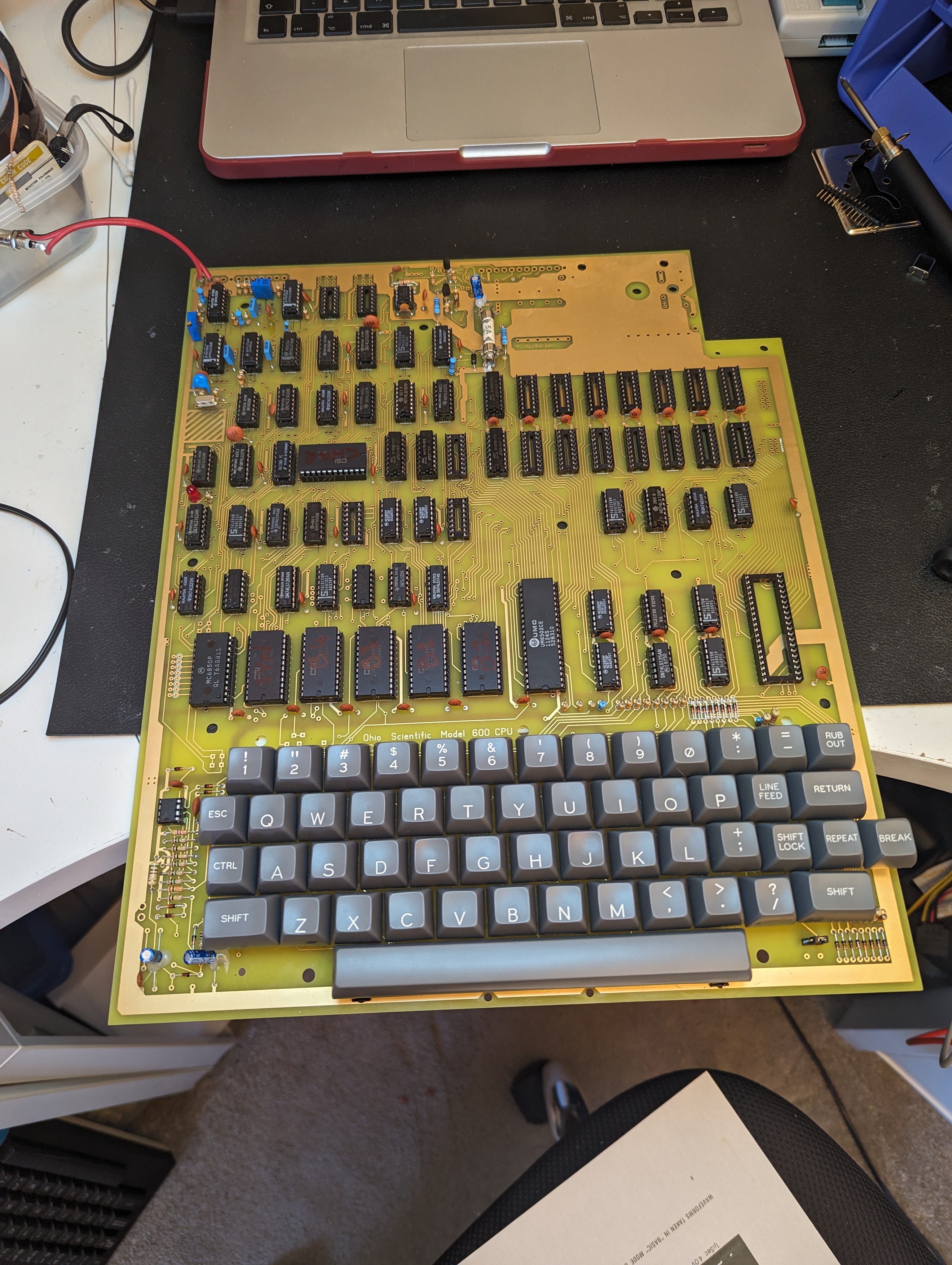
PXL_20240119_140541829.jpg (2.97 MiB) Viewed 2452 times

From what I can read in the assembly instructions, that should be enough for a basic test, however the machine does not boot, and there is no signal at the video out.

5v (4.99v at the ICs) is present across the board, I've tested all of the logic ICs, ROMs CPU etc for power. Power on LED illuminates as expected. I'm using a bench PSU set to 5v and 3A max, current draw is 1.25A, which seems about right based on what I've read.

I don't have over-voltage or under-voltage kicking in, though it is set to just over 5v and just over 3A.

However, there is no clock at pin 37 of the CPU, and as far as I am aware from working with 6502's before, that is clock in, with clock out on pin 39 and pin 3.

Starting at the crystal, I see 4Mhz (I couldn't get 3.9Mhz) on my 'scope clearly, but the Service Manual is suggesting that the clocks should be 3v peak to peak (I've assumed that, it doesn't say) at pin 8 of U58 and 4v P2P at pin 3 of U58.

Mine are more like 1v-1.5v, but I do get them. Also, if I check pin 8 of U43, I'd expect, based on the schematics in the Service Manual, to see the clock there too, but it isn't.

I did notice that on the same schematic, that there is something marked as W9, which I assume is a wire and either routes the clock signal directly out to the rest of the machine, or can route it via U29, a 7492.

Are these 'wires' in the service manual necessary for the Klyball board? I didn't see them in the build instructions (Or I missed them)

I have traced Pin 37 of the CPU back to pin 11 on U29, but the clock signal is super weak, in the order of a hundred or so millivolts IIRC.

If anybody has any thoughts I'd be grateful, Thanks.
User avatar
jbtech
Posts: 22
Joined: Mon Nov 13, 2023 12:33 am
Location: Australia
Contact:

Re: My Klyball 600D build

Post by jbtech »

Hi, I have recently built up the same reproduction PCB and have a couple of suggestions, your major issue at present does seem to relate to the clock signal though.

The circuit diagram included in the scan of the build instructions is a bit fuzzy so I also referred to a nice copy of the Rev. D schematic available from this site:

http://osi.marks-lab.com/boards/schematics/OSI600.pdf

The board should boot up with just 1kB of RAM (plus 1k video RAM) but they need to be installed into the pair of sockets nearest the edge of the PCB, in positions U31 and U45. If that does succeed the number of RAM bytes free should be 255.

Yes, there should be a good TTL level 0.98MHz clock signal at the CPU pin 37 which does come from U29 pin 11 but U29 should be a 7493 rather than a 7492. I seem to have made a similar error when I originally ordered ICs for the build, receiving a 7492 then realising the circuit called for a 7493 instead. Maybe somewhere in the documentation there is a typo, I can't recall why I originally ordered the 7492 as it is a divide by 12 counter rather than binary, divide by 16 so does not appear to be interchangeable.

Your clock signal levels at U58 do seem too low, are you seeing any signal at the output pin 8 of the 7486 U79 or input pin 1 of U29?

The link which is shown on the circuit diagram next to U29 is already connected in the default position within the PCB track layout and doesn't need to be changed or any wire link added in order to work.

Hope that helps, regards John
More from John's Retro Workshop http://www.jbtech.linkpc.net
bxdanny
Posts: 336
Joined: Thu Apr 16, 2015 2:27 pm
Location: Bronx, NY USA

Re: My Klyball 600D build

Post by bxdanny »

Also, U58 is shown on the OSI schematic as a standard 7400, rather than an LS series chip like most of the others. Is that what you are using? It may make a difference when interfacing with the crystal. Just a guess.
No current OSI hardware
Former programmer for Dwo Quong Fok Lok Sow and Orion Software Associates
Former owner of C1P MF (original version) and C2-8P DF (502-based)
Post Reply