I’m wondering if any OSI gurus out there might be able to help me with this problem?
I have a OSI 527 RAM expansion board I want to add to my cassette-based C4P.. . The board has some unconnected switches/jumpers on it. Apparently these can be used to specify exactly where you want to put the three 8k banks on the board in memory.
I don’t know how to jumper the board to do this? Does anyone know? I need the board to occupy a continuous 24k block of RAM starting at the end of the 8kRAM on the 502 board fitted, so I guess from 2000H onwards?
Some more info…
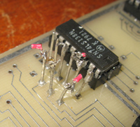
Here are the switch points (W1, W2 and W3) on my board which need bridging.
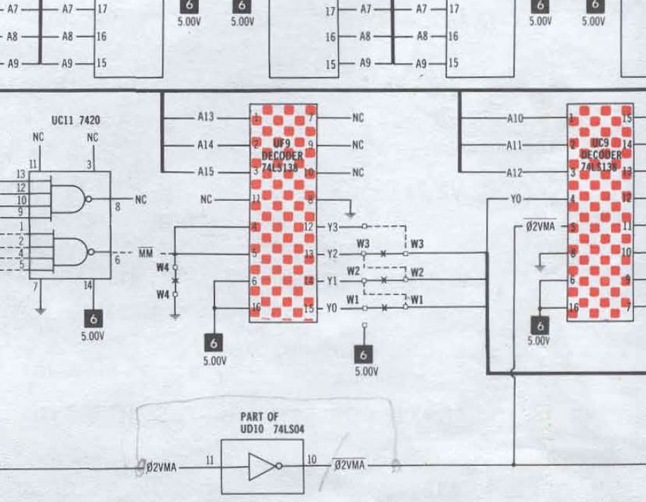
and here is the relevant part of the circuit diagram.
I found an article in "Micro: the 6502/6809 journal Vol 37 (June 1981)" which had a piece on adapting the OSI 527 board to a 600 Superboard. In that article was this statement:
"Jumpers W1, W2 and W3 at F9 determine the starting addresses of three independent 8k blocks of memory on 8k boundaries. No changes are made here...".
The 600 board has RAM (starts 0000H) and BASIC (starts A000H) which are at the same positions in memory as my 502 board so I figure that advice also applies to me.
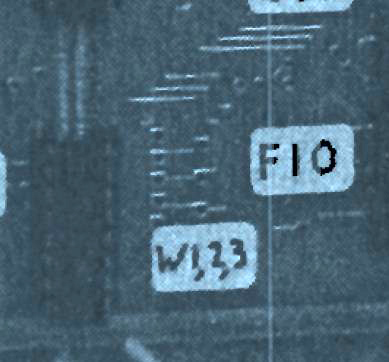
What is the default though? On my board it looks like there were default tracks connecting these switches but they have been completely scraped away. However using the low-res B/W photo in the article I can just see where these default tracks should go.
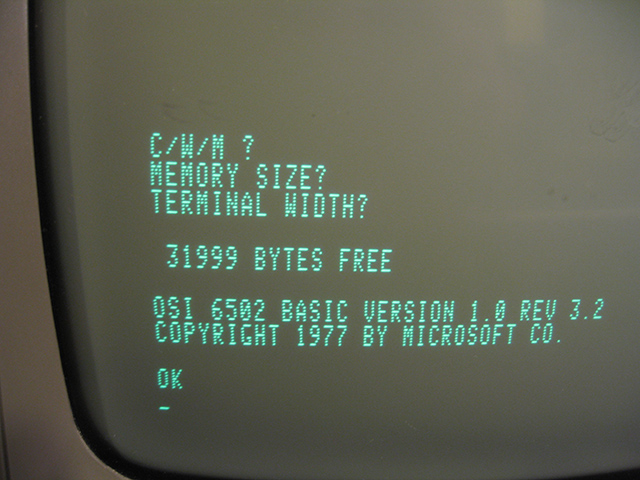
I wired up the system so the tracks connected as shows. Booting up the C4P now shows a RAM capacity of over 18000 bytes, which is progress So I am getting SOME of the RAM on the 527 board. With a fully populated RAM board plus the 8k on the 502 I should be seeing something close to 32k though, yes?
I could be a faulty RAM chip BUT I could also have those switches wrong? I don't want to try an diagnose a faulty RAM chip if it's the settings that are the problem. Can anyone verify they are correct for my configuration?
Any comments welcome.
Tez